

Foot switches can be used to turn electrical equipment on and off with the foot, freeing the hands to perform other operations or providing ergonomic improvement to a workstation. Foot switch and foot pedal applications often require specific electrical ratings, enclosures, pedal actions, cables, and other variations. This foot switch selection guide will help your sort through the options and features of electrical foot switches. When you’re ready to order, just select the product that you need and we’ll get it shipped to you as fast as we can. We also offer customization for manufacturers, and you can contact us today with your specifications.

Choose the Foot Switch That’s Right for Your Application
Safety and Selection WARNING: Before selecting or using any foot switch, read the foot switch safety warning. Only the user can be aware of all conditions and factors present during the installation, operation, and maintenance of a foot switch and the surrounding work area. Therefore, only the user can determine which foot switch(es) and which point-of-operation safeguards are required for a particular application or work station. Review OSHA and other regulations before selecting or installing any foot switch. This foot switch selection guide provides generalized information, and each application will require specific electrical and safety features. Safety options can include guards to protect against accidental activation, anti-trip safety latches (G-Series only), enclosures ratings, and front access gates.
Model Overview
The shape (form factor) and function required by a foot switch pedal application will help determine which model will be needed (in addition to electrical requirements). Some considerations discussed in using this foot switch selection guide include size, weight, material, shape, enclosure rating, guarding options, and other factors.


Foot Switch Pedal Action
There are two main types of pedal action: momentary and maintained.
1) Momentary Action: Press and hold to turn on, release to turn off (like a car horn). The user must continue to hold the pedal down to keep it on. As soon as the user lifts his or her foot, the unit will turn off. This is the most common type of foot switch pedal action.
2) Maintained Action: Press pedal once to turn on, press again to turn off (like a light switch). The foot switch will stay on and the user can remove his or her foot from the pedal until the user presses the pedal again to turn it off. Examples include G-Series -MA models (press down on pedal to turn it on, then press forward a latch inside the hood to return the pedal back to the off position), S420-Series models (press opposite ends of the pedal to toggle it on and off), and F300-Series models (has push on / push off maintained action, like a ball-point pen).
Additionally, the Anti-Trip Safety Latch is available on G-Series models. For this action, you have to press forward a latch inside the guard before you can press down on the pedal.
Electrical Circuitry and Contacts
Choosing the proper current and voltage rating for a foot switch application will depend on the electrical circuit of the equipment that the foot switch is attached to. The amount of electrical current that will flow through the circuit will determine the amperage rating required for the foot switch, as well as the gauge and type of cable. The voltage and horsepower ratings (if applicable) also must be selected appropriately for the application. Consult a certified electrician with any questions to determine the amperage, voltage, grounding, and power requirements for your application. Follow all local and national electrical safety regulations.
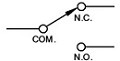
This foot switch selection guide can provide a general outline, but each application may have specific electrical and mechanical requirements. The foot switch wiring diagram may differ and be specific to each application, so be sure to follow all national and local electrical codes and best practices. Typically, foot switches contain SPDT contacts that are wired “normally open.” That is, the switch is open, or “off,” when not in use, and not activated until pressed. However, other circuit variations are available, and it will depend on the requirements for your application.
Foot Switch Wiring Diagrams and Circuit Images — Foot Switch Selection Guide
Many SSC Controls foot switches come with cables already attached. Two of the most common cable examples are listed below: cables with a piggyback plug, and cables with leads. Each of these cable configurations can be included on the S-Series, B-Series, and F-Series foot switch product lines. The circuits below are shown in the “off” or at-rest position, with the pedal fully up. Use this foot switch selection guide to help sort through wiring and circuit options.
Foot switch wiring diagram — Cables with piggyback plugs vs. cables with leads
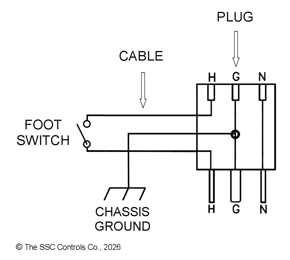
Foot switches — Cable with piggyback plug — Has piggyback (series) plug on the end of the cable. Comes pre-wired normally open (in “off” position until pressed).
Examples:

Wiring diagram — Foot switches with cable and piggyback plugs

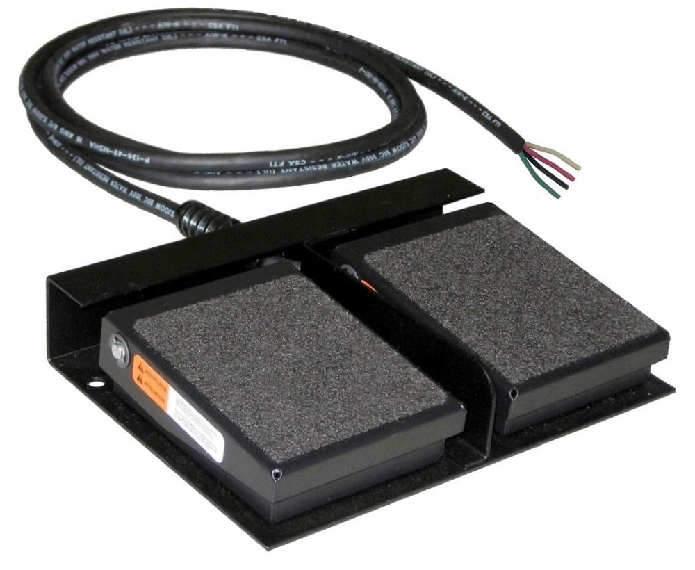
Foot switches — Cable with leads — Has leads on the end of the cable. Comes pre-wired normally open (in “off” position until pressed).
Examples:
Wiring diagram — Foot switches with cable and leads

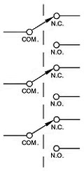
Foot switch wiring diagram — G-Series switch circuit diagrams
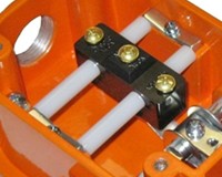
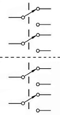
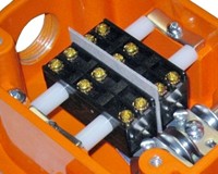
G-Series heavy-duty foot switches can include from one to three switches, and up to four independent SPDT circuits (see below for wiring diagrams). They typically do not come with cables. The user installs the appropriate cable and strain relief to the switch. G500 models have one switch, G502 models have two switches, and G503 models have three switches. This foot switch selection guide reviews the circuitry of some of the most common models. The circuits below are shown in the “off” or “at-rest” position, with the pedal fully up.

- Model example: G500-MO
- Circuit: SPDT (single-pole double-throw)
- Includes one SPDT switch for simple on/off.
- Ground screw location included on all models.
- Model example: G502-MO
- Circuit: DPDT (double-pole double-throw)
- Includes two SPDT switches that can be set to activate separately or at the same time.


- Model example: G503-MO
- Circuit: TPDT (triple-pole double-throw)
- Includes three SPDT switches that can be set to activate separately or at the same time.

- Model example: G504-MO
- Circuit: Dual DPDT (two DPDT switches in each unit)
- Ideal for controlling up to four independent circuits.
- Model example: G500-MO-DB
- Circuit: SPDT-DB (single-pole double-throw double-break)
- Double-break contacts make connection at two points on each line, enabling the switch to have improved performance and life in some DC circuits.
- Also called “Form Z” contacts.
- Order by selecting the “-DB” double-break option on the model page.


Additional notes:
- All foot switches should be properly grounded per local and national electrical codes.
- Two-stage models (models ending in “-2S”, such as G502-MO-2S) have an additional spring mechanism that provides an extra force in between the activation of each switch. The user will feel the additional force after activating the first switch when pressing halfway down on the pedal. He or she can then either hold at that position, or they can continue pressing the pedal down to activate the second switch.
- G-Series foot switches are available with other options, such as the Front Gate (-GT models), the Anti-Trip Safety Latch (-AT), and Maintained Action (-MA). However, the switch circuitry shown above generally stays the same for these options.
- We also sell replacement parts, including the switch block, for many models.
Foot Switch Wiring and Installation (For One SPDT Circuit Wired Normally Open)
Warning: Disconnect input power before installing or servicing any foot switch. Please review the Foot Switch Safety and Selection WARNING before selecting, installing, servicing, or using any foot switch. The buyer (and user) is responsible for proper foot switch selection, installation, safety, and application. The following installation instructions are general guidelines, and each application may require steps or connections different from those listed below.
Foot switches that come with the piggyback plug (3-pronged NEMA 5-15 series P/R):
Foot switches that come with cable that have leads (wires) on the end of the cable:
Foot switches that come with no wiring or cable:
Enclosure Rating — Foot Switch Selection Guide
In addition to electrical ratings and the size or shape of the foot switch, the enclosure rating is one of the most important factors to consider when choosing a foot switch for a particular application. Foot switches typically require one of the following enclosure ratings (for non-hazardous locations), as defined by UL, CSA, and NEMA (see also www.ssccontrols.com/enclosures):
Additional References and Safety Warnings
- SSC Controls — Glossary
- SSC Controls — Foot Switch Safety Warning
- Machine guarding of presses (OSHA)
- Occupational Safety and Health Association (OSHA)
- National Electrical Manufacturers Association (NEMA) — Enslosure Types
- Switch circuitry and switches from Wikipedia
- General resource about electric circuits from allaboutcircuits.com
Cable and Connector Options
Foot switches can be shipped with a variety of cable options (see examples below), connectors, and plugs. Modifications for OEM applications (anything that is not a standard SSC product, as listed on the product pages) typically require a 100 unit minimum. For information about special OEM modifications, please contact us by phone at 1-440-205-1600 or by email.